článek převzán ze stránek: http://www.insidemylaptop.com

In the following guide I explain how to disassemble HP Pavilion dv6500, dv6600, dv6700, dv6800 notebooks. In this particular case I’m taking apart an HP Pavilion dv6700 notebook.
I believe this guide will work for some other models in the Pavilion dv6000 line.
You can use these instructions for removing and replacing all main notebook components.
If you need spare parts for HP Pavilion dv6500/dv6600/dv6700/dv6800 notebooks, you can search here.
Turn off the notebook and unplug the AC adapter.
STEP 1.
Remove the battery.
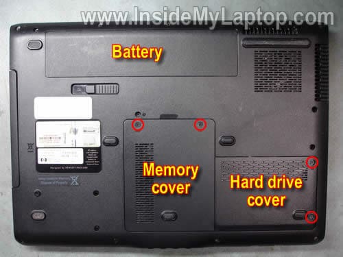
Remove four screws securing the hard drive and memory (RAM) covers. Remove both covers.
STEP 2.
Lift up the right side of the hard drive assembly to disconnect it from the motherboard.
Remove the hard drive assembly.

STEP 3.
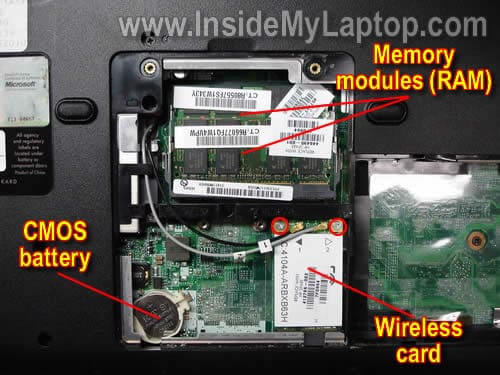
Remove both memory (RAM) modules.
Disconnect two antenna cables (black and gray) from the wireless card. Remove two screws securing the wireless card to the motherboard. Remove the wireless card.
By the way, in this step you can access the CMOS (RTC) battery.
STEP 4.
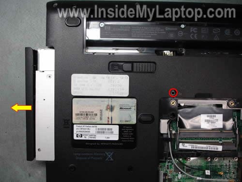
Remove one screw securing the CD/DVD drive to the laptop base.
Pull the CD/DVD drive from the notebook and remove it.
STEP 5.
Remove all screws from the bottom of the notebook.
Do not forget:
– three screws in the CD/DVD drive bay (yellow).
– one screw in the hard drive bay (green).
– two hex studs under memory slots (orange). Use 3/16 nutdriver.
Mark all removed screws somehow so you don’t forget their location when assemble the notebook back together.

STEP 6.
Carefully lift up the right side of the power button board cover.

There are two cables connected to the motherboard. We’ll disconnect these cables after removing the keyboard in the STEP 8.

STEP 7.
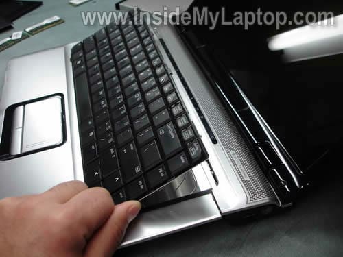
Now, when the power button board cover separated from the laptop case, you can remove the keyboard as it shown on the picture below.
STEP 8.
Carefully disconnect the keyboard cable from the motherboard.
For more detailed keyboard removal instructions please follow this guide for HP Pavilion dv6000 laptop.
These instructions should be identical for HP Pavilion dv6500, dv6600, dv6700, dv6800 notebooks.

STEP 9.
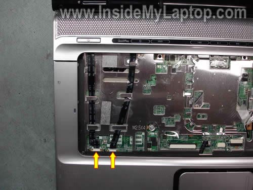
Disconnect two cables running from the power button boar cover.
There are no locks on these connectors. Simply pull both cables from connectors.
STEP 10.
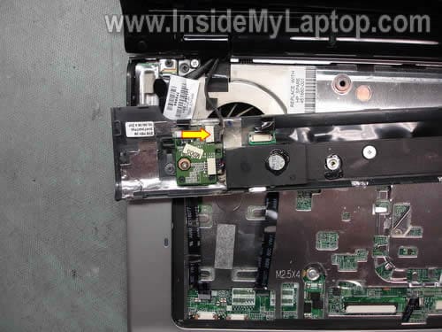
Turn the cover upside down and disconnect one cable from the power button board.
STEP 11.
Remove the cover.

STEP 12.
Disconnect the video cable connector from the motherboard.
This connector is located close to the left display hinge.

STEP 13.
Pull both wireless card antenna cables through the opening in the top cover. Unroute both antenna cables.
Remove two screws securing the display assembly hinges.

STEP 14.
Lift up and separate the display assembly from the notebook base.
In one of the previous posts I explain how to disassemble the display assemble and remove the LCD screen from an HP Pavilion dv6000.
These instructions should be identical for HP Pavilion dv6500, dv6600, dv6700, dv6800 notebooks.

STEP 15.
Remove five screws securing the top cover assembly.
Disconnect the touch pad cable from the motherboard.

STEP 16.
Start separating the plastic cover from the notebook base. You can use a piece of soft plastic (I’m using a guitar pick) to separate the cover from the base.

The cover has been removed.

STEP 17.
Separate the top cover assembly from the notebook base.

Again, as a case cracker I’m using the same guitar pick.

STEP 18.
Remove the top cover assembly.
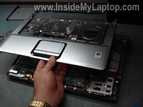
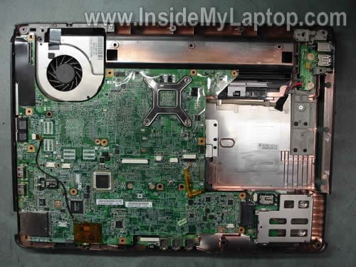
The top cover assembly has been removed.
STEP 19.
Disconnect the Bluetooth module cable from the motherboard.
Remove two screws securing the Bluetooth module.
Remove the module.

STEP 20.
Remove four screws securing the express card slot.
Slide the slot board to the right and disconnect it from the motherboard.

STEP 21.
There is only one screws securing the motherboard to the notebook base.
Remove these screw.

STEP 22.
Start removing the motherboard as it shown on the picture below.
When the motherboard is lifted up, disconnect one cable from the audio board.
There are two more cables connected to the motherboard and we’ll remove them in the next step.

STEP 23.
Turn the motherboard upside down and disconnect two more cables.

STEP 24.
The motherboard has been removed.
The audio board and power connector board are still connected to the notebook base.

STEP 25.
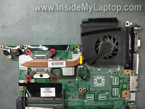
Loosen four screws securing the cooling assembly (heat sink and fan) to the motherboard.
STEP 26.
Lift up and remove the cooling assembly.
Now you can access the processor (CPU).

In this model the power connector (DC power jack) is not soldered directly to the motherboard.
The power connector is mounted on a separate board.
If the power connector fails, you can desolder it from the board and replace with a new one or replace the entire power connector board.

